
You don’t have to be a dedicated follower of the transportation industry to know it is in the early stages of a significant transition, away from the rumbling internal combustion engine to the quiet days of electric vehicles. The signs of this transition are right there on the streets in the form of electric-powered buses, bikes and cars. The road to our electric future is before us, but we won’t be getting there without compound semiconductors like SiC.
Manufacturers in the automobile and clean energy sectors want more efficient power devices that can accommodate higher voltages, possess faster switching speeds and offer lower losses than traditional silicon-based power devices, something SiC power devices with trench structures can deliver.
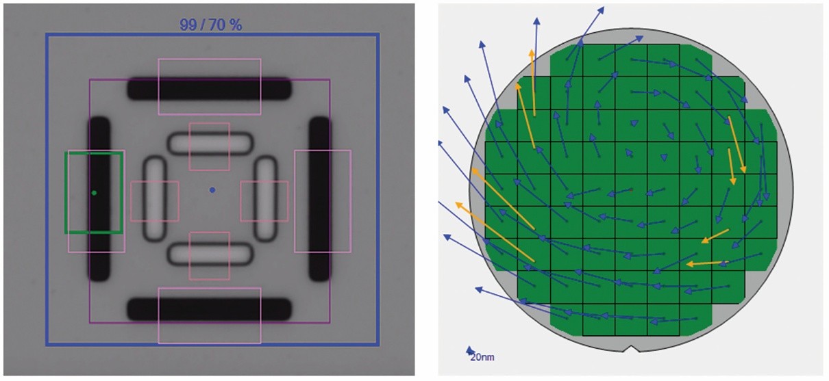
But while trench-based architectures offer reduced on-resistance and increase carrier mobility, they bring along increased complexity. For manufacturers of SiC power devices, the ability to accurately measure epi layer growth and the depth of implant layers in these trenches is of considerable concern, especially when faced with ever-increasing fabrication complexity.
In the previous blog in this series, we explored how using an FTIR-based system allows for the direct modeling of carrier concentrations and film thickness, thus enabling SiC power device makers to better measure epi layer growth, implant layers and composition. In this installment, we explore how manufacturers of SiC power devices with trench-based structures measure trench depth and bottom and top critical dimension (CD) by using an optical critical dimension (OCD) metrology system designed for specialty devices.
The figures alone are impressive: SiC power devices are experiencing an annual average growth rate approaching 34% through 2027, according to the Yole Group. However, the potential for this amongst other compound semiconductor-based power devices such as gallium nitride (GaN) to change the world around us is even more impressive.
Thanks to the role that SiC-based devices play in the increased electrification of automobiles and the sustainable energy movement, the effort to make this world a cleaner, greener place is no longer a wished-for science fiction fantasy. It may one day be our reality. Perhaps even soon.
Manufacturers in the automobile and clean energy sectors want power devices that are more efficient and can accommodate higher voltages, faster switching speeds and lower losses than traditional silicon-based power devices. To accomplish this, they are turning to higher efficiency silicon carbide (SiC)-based devices.
When it comes to SiC power devices, most manufacturers have adopted a trench-based architecture. This reduces on-resistance and increases carrier mobility. However, these improvements come at the expense of rising fabrication complexity.
To address this issue, high-volume manufacturers of SiC power devices are, at several key steps, adopting inline process control methods, including optical metrology techniques like Fourier transform infrared (FTIR). With a system supporting FTIR optical metrology at their disposal, manufacturers can more accurately measure epi layer growth and the depth and accuracy of implanted dopants across the wafer, key challenges posed by the increased fabrication complexity of SiC power devices. In this blog, we’ll discuss how FTIR technology can help manufacturers successfully address these challenges.
What is 4D InSpec?
A handheld, 3D surface measuring gauge. It takes a measurement in about 1-2 seconds, in-situ. It’s highly accurate, with micron-level precision. The instrument was first used for measuring defects on precision machined parts. It quickly assesses scratches, pits, nicks, corrosion and other defects, and assures the quality of features like peening, scribe marks, edge blending and rivets. Its analysis software measures and quantifies edge break, radius of curvature with high precision. It’s easily set up for pass-fail analysis. 4D InSpec improves profitability in repair and new-make manufacturing processes in the aviation, automotive, nuclear and general precision machining sectors.
Why
Consider your highest-value part. If you could reduce the number of those that are
scrapped or reworked via inaccurate inspection by 40%, how much money would that save you?
What
The 4D InSpec surface measuring gauge produces fast, numerical, objective surface
information needed to assess components. By quantifying quickly and easily, customers have reported a 20-40% increase in yield.
Who & Where
The instrument instantly reports defect statistics on precision machined
parts, and is transforming throughput in the MRO process for the aviation, automotive and nuclear energy industries. It is also used in industries as diverse as furniture, cutting tools, saw blade, and solar tile manufacturing.
Benefits
• High precision, quantified measurements increase yield by saving more parts
• Return on investment is normally days to weeks
• Records reliable, repeatable results you can share to prove your outcomes
• Reduces labor by saving on dismantling and part transportation
• Improves turnaround time by eliminating waiting, increasing throughput

You Have a Challenge? Let’s talk.
We’d love to connect with you.
Looking to learn more about our innovative solutions and capabilities? Our team of experts is ready to assist you. Reach out today and let’s starts a conversation about how we can help you achieve your goals.
Let’s Talk
"*" indicates required fields
Efforts at curbing carbon dioxide emissions are stepping up, with more electric vehicles on our roads and the installation of renewable energy sources on the rise. Alongside these advances, the makers of these green technologies are increasing the electrical efficiency of their offerings, with silicon-based power devices being ditched in favour of superior alternatives based on the likes of SiC.
Supporting this move are the superior physical properties of these compounds. Compared with silicon, semiconductors such as SiC have wider-bandgaps, a higher electron saturation velocity, a higher critical electric field and a larger thermal conductivity. Drawing on all these strengths, power transistors offer higher operating frequencies, higher power ratings, elevated operating temperatures, better cooling capability and lower energy loss – just the traits that the market wants.
In recent years, power semiconductor applications have expanded from industrial and consumer electronics to renewable energy and electric vehicles. Looking to the future, the most promising power semiconductor devices will be insulated gate bipolar transistor (IGBT) and power metal oxide semiconductor field effect transistor (power MOSFET) modules.
During the manufacturing of these devices, metal films are deposited on the die of MOSFET and IGBT power devices. These layers of film have two main functions: they connect the elementary cells constituting the power dies to the source (power MOSFET) or emitter (IGBT) and allow for the welding of bond wires on the chip or for the solder bonding, facilitating thermal conduction. Because power devices run high currents at high-operating temperatures, the metal layers need to be properly controlled for electrical properties and thickness to enhance thermal conductivity.
Furthermore, power devices are transitioning from 6-inch to 8-inch wafers; this is happening at the same time as process windows are shrinking. As a result, measuring multi-layer metal thickness accurately and characterizing the uniformity of metal film deposition at the wafer edge has become increasingly important. For example, the front side of wafers requires deposition of a thick metal layer, typically 5µm or more of aluminum alloy. The uniform coverage of aluminum to conduct high currents across the entire wafer is key to device yield and reliability.
You’ve read the reports: the memory market is floundering as the semiconductor industry moves through another scarcity/surplus cycle.
Be that as it may, innovation is happening as the industry continues to pursue increasingly higher three-dimensional stacks, with 3D NAND stacks taller than 200 layers entering production.
However, there are challenges. Among those: conventional optical critical dimension (OCD) metrology systems have difficultly measuring the tungsten (W) recess in the wordline (WL) slit following the replacement gate step. This is particularly a problem as high-aspect ratio (HAR) stacks reach 96 layers or higher. For manufacturers, the ability to measure the W recess is critical. Under-etching the W replacement gates in the recess can cause wordlines to short, while over-etching the W gates can damage cells or cause a short from the wordline to the source line.