
In industries such as aircraft engines automotive, companies need to rapidly establish the quality of components, both during production and during repair and overhaul. Many of these components are highly valuable and complex, often with hundreds of features requiring inspection.
To date, much of this inspection has been completed manually—a slow and subjective process. A new, automated system is now being adopted for rapid, repeatable, non-contact measurement of features and defects on precision machined parts. Combining the flexibility of an industry-proven optical gage and
robotic automation, the system dramatically improves inspection throughput and reliability, recording quantitative data that can be tracked throughout the component’s lifetime.

You Have a Challenge? Let’s talk.
We’d love to connect with you.
Looking to learn more about our innovative solutions and capabilities? Our team of experts is ready to assist you. Reach out today and let’s starts a conversation about how we can help you achieve your goals.
Let’s Talk
"*" indicates required fields
Abstract
The growing demand for heterogeneous integration is driven by the 5G market. This includes smartphones, data centers, servers, high-performance computing (HPC), artificial intelligence (AI) and internet of things (IoT) applications. Next-generation packaging technologies require tighter overlay to accommodate larger package sizes with fine-pitch chip interconnects on large-format flexible panels. Heterogeneous integration enables device performance gains by combining multiple silicon nodes and designs inside one package. The package size is expected to grow significantly, increasing to 75mm x 75mm and 150mm x 150mm, within the next few years. For these requirements, an extremely large exposure field fine-resolution lithography solution was proposed to enable packages well over 250mm x 250mm without the need for image stitching, while exceeding the overlay and critical uniformity requirements for these packages.
One of the challenges of extremely large exposure field fine-resolution lithography is to achieve an aggressive overlay number. Formation changes experienced by the panel as a result of thermo, high-pressure and other fan-out processes shift the design location from nominal coordinates; this causes inaccurate overlay and low-overlay yield in the lithography process. Addressing this critical lithography challenge becomes an important task in heterogeneous integration.
In this paper, a 515mm x 510mm Ajinomoto build-up film (ABF)+copper clad laminate (CCL) substrate is selected as the test vehicle. We will analyze the pattern distortion of an ABF+CCL substrate to understand the distribution of translation, rotation, scale, magnification, trap, orthogonality and other errors in the substrate, and then use extremely large exposure field fine-resolution lithography to address the pattern distortion of the substrate. This demonstration will provide an analysis of panel distortion and detail how the extremely large exposure field fine-resolution lithography solution addresses panel distortion to achieve an aggressive overlay number.
The growing demand for heterogeneous integration is driven by the 5G market that includes smartphones, data centers, servers, HPC, AI and IoT applications. Next-generation packaging technologies require tighter overlay to accommodate a larger package size with finer pitch chip interconnects on large format flexible panels.
Heterogeneous integration enables next-generation device performance gains by combining multiple silicon nodes and designs inside one package. The package size is expected to grow significantly, increasing to 75 x 75 mm and 150 x 150 mm, within the next few years. For these requirements, an extremely large exposure field with fine resolution lithography will enable packages well over 250 x 250 mm without the need for image stitching while exceeding aggressive overlay and critical uniformity requirements for these packages.
The lithography challenge to fulfill the need of heterogeneous integration is the limitation of exposure field size of the currently available solutions in the market. Multiple shots with stitching is used and this affects not only productivity performance but potential yield loss at the stitching boundary. Addressing the critical lithography challenges described above becomes an important task in heterogeneous integration, and an extremely large exposure field with fine resolution lithography is one of the best solutions for this task.
In this paper, a 515 mm x 510 mm panel is selected as the test vehicle, and we will demonstrate an extremely large exposure field with fine resolution technology on this panel. This demonstration provides the results and details about how this new technology will address the challenges of large package size processes.
The growing demand for heterogeneous integration is driven by the 5G market that includes smartphones, data centers, servers, HPC, AI and IoT applications. Next-generation packaging technologies require tighter overlay to accommodate a larger package size with finer pitch chip interconnects on large format flexible panels.
Fan-out panel level packaging (FOPLP) is one of the technologies that is able to achieve market requirements, but also faces several signification processes challenges. One critical challenge for FOPLP is die placement error, which is a result of the reconstitution process. Die placement error can cause high overlay error, which induces low overlay yield. To address this situation, site by site correction exposure with feedforward lithography is proposed. Site by site correction exposure can overcome the die placement error to achieve an acceptable overlay yield, and feedforward lithography is used to improve the throughput when using site by site correction exposure. An issue was observed when using feedforward site by site correction method: when one or more reconstituted dies suffered large displacement error, these large error dies affect the correctable accuracy of the site and induce poor overlay to all the dies in the site. To address this issue, which could induce poor overlay, advanced outlier control technology is proposed. Advanced outlier control technology is used for identifying the large error dies and processing these large error dies to prevent the situation.
In this paper, we demonstrated advanced outlier control technology with feedforward lithography on a selected test vehicle, which is a 510 mm x 515 mm panel. 400 simulation dies were built on this panel and part of the dies were designed with a large displacement error. The panel was processed using advanced outlier control technology with feedforward lithography in the demonstration. This demonstration showed how these two technologies integrated together and how this integration strategy worked for the FOPLP process. We also review and discuss the results for how this integration technology can maintain yield and throughput under such challenging conditions.
The following paper presents a case study describing how to improve yield and fab productivity by implementing a frequent pattern database that utilizes Artificial Intelligence based Spatial Pattern Recognition (SPR) and wafer process history. This is important because associating spatial yield issues with process and tools is often performed as a reactive analysis, resulting in increased wafer scrap or die loss that could be prevented. The implementation of fab fingerprint technology proactively generates a pareto of high impacting process steps and tools based on a pattern score, enabling the production team to concentrate more efficiently on yield limiting events.
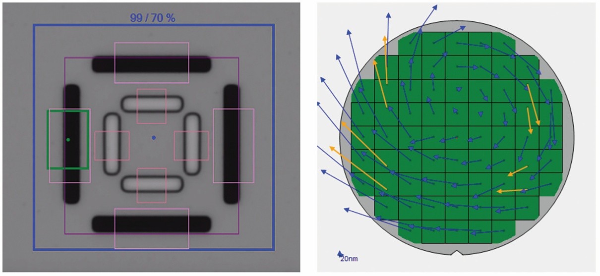
Optically opaque materials present a series of challenges for alignment and overlay in the semi-damascene process flow or after the processing of the magnetic tunnel junction (MTJ) of a Magnetic Random-Access Memory (MRAM). The overlay and alignment of a lithographically defined pattern on top of the pattern and the underlying layer is fundamental to device operation in all multi-layer patterned process flows. There are a wide variety of optical techniques and specially designed targets (Figure 2) that are used to address this problem in conventional flows. Typically, either an ultraviolet, visible, or infrared light is coupled through the top photoresist layer or an etched hard mask to be aligned to the bottom layer [1]. However, in some MRAM flows this coupling may not be possible as there may be an intervening opaque layer (Figure 1). In such cases, conventional methods of alignment using light fail. To overcome this issue, extra patterning operations may be used to open areas around the alignment features, but these operations add significant process cost.
In this paper we evaluate the use of picosecond laser acoustics (PLA) measurement as an alternative method to characterize the overlay and alignment patterns that are embedded under opaque metal films. We selected the MRAM process flow for this study where the different overlay and alignment markers were underneath opaque layers including an MTJ layer. These specific markers are imaged with the help of PLA employing an ultrafast laser in a pump and probe configuration to generate and detect acoustic waves capable of propagating through optically opaque layers. This technique, in sharp contrast with other competing acoustic imaging techniques such as scanning acoustic microscopy (SAM) [5,6], does not require the sample to be submerged in a coupling medium such as water.