
In recent years, power semiconductor applications have expanded from industrial and consumer electronics to renewable energy and electric vehicles. Looking to the future, the most promising power semiconductor devices will be insulated gate bipolar transistor (IGBT) and power metal oxide semiconductor field effect transistor (power MOSFET) modules.
During the manufacturing of these devices, metal films are deposited on the die of MOSFET and IGBT power devices. These layers of film have two main functions: they connect the elementary cells constituting the power dies to the source (power MOSFET) or emitter (IGBT) and allow for the welding of bond wires on the chip or for the solder bonding, facilitating thermal conduction. Because power devices run high currents at high-operating temperatures, the metal layers need to be properly controlled for electrical properties and thickness to enhance thermal conductivity.
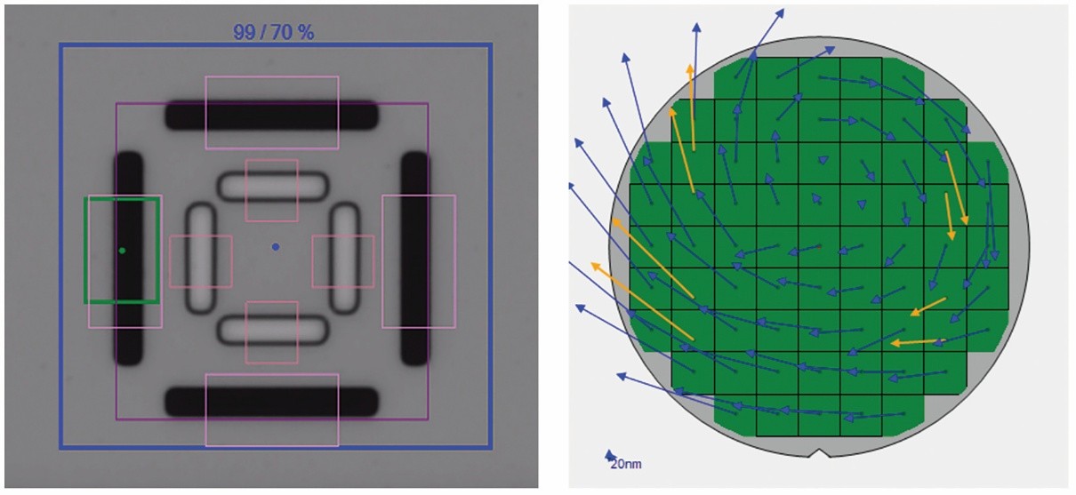
Furthermore, power devices are transitioning from 6-inch to 8-inch wafers; this is happening at the same time as process windows are shrinking. As a result, measuring multi-layer metal thickness accurately and characterizing the uniformity of metal film deposition at the wafer edge has become increasingly important. For example, the front side of wafers requires deposition of a thick metal layer, typically 5µm or more of aluminum alloy. The uniform coverage of aluminum to conduct high currents across the entire wafer is key to device yield and reliability.
“When will glass replace copper clad laminate on advanced IC substrates?”
That’s a question many on the heterogeneous integration (HI) side of the semiconductor industry are asking. Unfortunately, the answer is not straightforward.
But before we get to answering that, let’s take an advanced IC substrate (AICS) refresher. In other words, how did we get to the point where glass substrates have become a topic of discussion?
AICS provides a means to connect chiplets and passives with extremely high I/O count to the printed circuit board (PCB). In the process, AICS has facilitated a paradigm shift in packaging technology with the introduction of HI. This revolutionary approach to packaging provides a significantly cheaper alternative to silicon interposer technology, which is limited in the package sizes it can support.
The AICS is built around a fiberglass resin core with copper on both sides. This is known as copper clad laminate (CCL). The CCL facilitates the creation of redistribution layers (RDL) that connect through the substrate core with plated through holes (PTH). The RDLs are separated by organic dielectric layers known as build-up films.
You’ve read the reports: the memory market is floundering as the semiconductor industry moves through another scarcity/surplus cycle.
Be that as it may, innovation is happening as the industry continues to pursue increasingly higher three-dimensional stacks, with 3D NAND stacks taller than 200 layers entering production.
However, there are challenges. Among those: conventional optical critical dimension (OCD) metrology systems have difficultly measuring the tungsten (W) recess in the wordline (WL) slit following the replacement gate step. This is particularly a problem as high-aspect ratio (HAR) stacks reach 96 layers or higher. For manufacturers, the ability to measure the W recess is critical. Under-etching the W replacement gates in the recess can cause wordlines to short, while over-etching the W gates can damage cells or cause a short from the wordline to the source line.
All great voyages must come to an end. Such is the case with our series on the challenges facing the manufacturing of advanced IC substrates (AICS), the glue holding the heterogeneous integration ship together.
In our first blog, we examined how cumulative overlay drift from individual redistribution layers could significantly increase overall trace length, resulting in higher interconnect resistance, parasitic effects and poor performance for high-speed and high-frequency applications. To address this, layer to layer overlay performance data needs to be monitored at each layer. If the total overlay error exceeds specifications at any process step, and at any location on the panel, corrective action must be taken to mitigate the drift in total overlay.
For this second installment, we explored the issue of AICS package yield and its importance in fostering a cost-effective, production-worthy process. Unlike most fan-out panel-level packaging (FOPLP) applications, AICS has relatively few packages per panel. This enormous disparity impacts yield calculations dramatically. In the AICS production process, the main challenge is the real-time tracking of yield for every panel, at every layer, throughout the fab. The solution: using advanced automatic defect classification (ADC) and yield analytics to quickly address errors.
In this final article of the series, we explore how overlay correction solutions compensate for panel distortion effects induced by copper clad laminate (CCL) processing, which impacts yield and final package performance.
With the continued advancement of environmental, social and governance goals, corporations are increasingly focused on reducing their carbon footprints. To accomplish this, these companies are being asked to operate their businesses more efficiently than ever before, whether the matter is reducing waste, water usage or power consumption. This is true for the semiconductor industry as well.
Although semiconductor manufacturing is not a smokestack industry, it is truly amazing just how many resources – from water to materials and electricity – goes into making chips. To better understand the carbon footprint and environmental impact a typical fab has, consider this: based on estimates in a 2021 article in The Guardian, a 1% improvement in a factory’s production capability could save that factory 450 tons of waste, 37 million gallons of fresh wafer and 22.5 million kilowatt-hours of electricity over the course of a year. That small 1% change is a substantial reduction in resources used, one that not only makes operations managers happy but ESG-minded stockholders as well.
No matter how you get your news, it seems like everyone is talking about AI – and it’s either going to usher in a new era of productivity or lead to the end of humankind itself. Regardless, the AI era is here, and it’s just beginning to have an impact on our lives, our jobs and our future.
To meet the rigorous demands of AI – along with high-performance compute, 5G and electric vehicles – the semiconductor industry is seeking out new innovations to increase speed, bandwidth and functional density, lower energy usage, cost and latency. At the top of the list: heterogeneous integration. And to make heterogeneous integration a reality, back-end packaging houses use advanced integrated circuit substrates (AICS).
In a previous blog, we focused on one of the major challenges of manufacturing AICS – total overlay drift. For this second installment in our three-part series on packaging solutions, we explore the issue of AICS package yield and its importance in fostering a cost-effective, production-worthy process.