
Over the past ten years, primarily driven by a tremendous expansion in the availability of data and computing power, artificial intelligence (AI) and machine-learning (ML) technologies have found their way into many different areas and have changed our way of life and our ability to solve problems. Today, artificial intelligence and machine learning are being used to refine online search results, facilitate online shopping, customize advertising, tailor online news feeds and guide self-driving cars. The future that so many have dreamed of is just over the horizon, if not happening right now.
The term artificial intelligence was first introduced in the 1950s and used famously by Alan Turing. The noted mathematician and the creator of the so-called Turing Test believed that one day machines would be able to imitate human beings by doing intelligent things, whether those intelligent things meant playing chess or having a conversation. Machine learning is a subset of AI. Machine learning allows for the automation of learning based on an evaluation of past results against specified criteria. Deep learning (DL) is a subset of machine learning (FIGURE 1). With deep learning, a multi-layered learning hierarchy in which the output of each layer serves as the input for the next layer is employed.
Currently, the semiconductor manufacturing industry uses artificial intelligence and machine learning to take data and autonomously learn from that data. With the additional data, AI and ML can be used to quickly discover patterns and determine correlations in various applications, most notably those applications involving metrology and inspection, whether in the front-end of the manufacturing process or in the back-end. These applications may include AI-based spatial pattern recognition (SPR) systems for inline wafer monitoring [2], automatic defect classification (ADC) systems with machine-learning models and machine learning-based optical critical dimension (OCD) metrology systems [1][7].
FAN-OUT PANEL LEVEL PACKAGING (FOPLP) has multiple benefits in advanced packaging applications, including enhanced connectivity and reduced costs. FOPLP differs from wafer-level packaging processes in that FOPLP utilizes large, rectangular panels rather than the round silicon wafers typically associated with IC manufacture. FOPLP’s rectangular panels more efficiently fit rectangular die, which can reduce costs since manufacturers can process more packages in each run.
Despite many advantages, FOPLP also faces specific challenges, such as yield loss caused by inaccurate die placement and the resulting overlay errors. In this context, dies with unusually large placement errors, or outliers, can be especially troublesome. These outliers cause losses of both the misplaced die and surrounding dies. However, integrating outlier control with feedforward metrology can greatly improve both yield and throughput.
Fan-out processes cut individual dies from the wafer and reconstitute them on a processing substrate separated by additional space. Subsequent steps fabricate redistribution lines in multiple layers and end with the creation of contacts on the surface of the package. The area available for contacts is increased by the additional space between chips, allowing more contacts per chip.
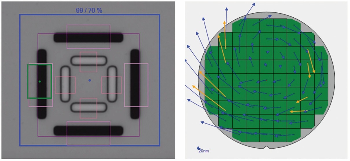
One critical challenge for FOPLP is die-placement error. This error originates during the robotic pick-and place operation in which chips are positioned on the reconstitution substrate. The problem arises when die positions shift during subsequent processing steps. If uncorrected, these die-placement errors can result in overlay errors and reduced yield. While die-placement errors can be measured and corrected, die-by-die in the lithography tool, this greatly reduces throughput. Feedforward lithography, which measures placement errors and calculates corrections in a separate system and then feeds the corrections forward to the lithography system is much faster. Lithography throughput can be further increased by including more than one die in each exposure site and then applying site-by site corrections to the exposures.
In this scheme, dies with unusually large placement errors can have an outsized impact on yields by skewing the site correction to such a degree that the site correction causes unacceptable overlay errors for all dies in the site. A solution: advanced outlier control technology (Figure 1). This technology detects outliers and excludes them from the correction calculation, thereby sacrificing the outlier to optimize overall yield and throughput.
Rapidly growing demand for new types of functionality across an expanding range of applications, including 5G communication, smartphones, data centers, servers, high- performance computing (HPC), artificial intelligence (AI) and the Internet of Things (IoT), is driving a fundamental shift in the way electronic devices are designed and manufactured. Gone are the days when advances were defined by an increasing number of shrinking transistors with ever-faster switching times and lower power consumption, all fabricated as a single, monolithic integrated circuit (IC). Many of today’s most advanced systems integrate multiple die, each optimized for a specific capability and fabricated with a process designed specifically for that type of circuit. These disparate chips are then connected using advanced packaging (AP) technologies, a process known as heterogeneous integration (HI).
One example of HI uses advanced IC substrates (AICS) in a process known as ultra-high density (UHD) panel fan-out. This fan-out panel level process (FOPLP) is a redistribution lines (RDL)-first approach, where many layers of patterned conductive and insulating material are processed on both sides of a large panel to route electrical signals between the integrated chips, which are added last. Once the RDL layers are complete, solder bumps are added to form connection points that will mate with matching connection pads on the component ICs. Package substrate sizes are expected to reach 150mm x 150mm in the next few years. Panels, which may be 500mm x 500mm or larger, can accommodate many more packages per panel than the substrates used in wafer-level processes, which are restricted to round, wafer-like substrates of 300mm or less in diameter.
The lithography challenge for large heterogeneous integration is the limited size of the exposure field (typically 60mm x 60mm or less) for most currently available lithography systems. Smaller-field systems can be used to pattern large substrates by stitching together multiple exposures, but this affects both productivity and yield because of the need for multiple exposures of multiple reticles and the risk of errors at the stitching boundaries. A large exposure field would eliminate these impediments. However, there are also challenges associated with a large exposure field. These include panel warpage and distortion, which can impact critical dimensions, uniformity and overlay.
We describe here the use of our large-field lithography system (JetStep® X500) to expose 250mm x 250mm substrates in a single shot on 515mm x 510mm panels. Our evaluation included: 1) critical dimension (CD) control for 3m, 5µm and 6µm lines/spaces, and 15μm and 20μm vias; 2) CD uniformity across the exposure field; and 3) overlay accuracy. We used copper clad laminate (CCL) and Anjinomoto build-up film (ABF) panels for resolution, and glass panels with liquid resist for overlay and uniformity. The large field eliminates stitching, allows the exposure of more large package substrates in a single shot and requires fewer shots to complete a panel. We compares the exposure layout for a large field (250mm x 250mm) and a smaller field (59mm x 59mm) on a 510mm x 515mm panel. With the large exposure field, the panel can be completely exposed with just four shots, while the smaller field requires 64 shots.
Vacuum based processes are essential in the semiconductor manufacturing process. In the simplest terms, integrated circuits are composite structures fabricated one layer at a time. Each layer is deposited as a blanket film, then patterned by removing material in selected areas. The final, three-dimensional structure, made up of insulating, conducting, and semiconducting components, forms a functional circuit. Most of the deposition and removal steps take place in a vacuum environment, which creates the physical conditions required for the process to proceed, ensures the purity of the material deposited, and removes excess process chemicals and by-products from the process chamber. Throughout its history, the semiconductor industry has defined progress almost exclusively by its ability to reduce the size of the devices it creates. Measuring critical dimensions of the component structures and controlling the manufacturing process to ensure high yields of functional devices have been a critical requirement for progress. These structures became too small to resolve with image based light microscopy decades ago. Manufacturers now rely on scatterometry for optical critical dimension (OCD) measurements. Because it is not image based, scatterometry is not constrained by the diffraction effects that limit image resolution. Furthermore, and especially important for current device architectures, scatterometry can provide three-dimensional measurements. In this article we will look at the fundamentals of OCD and provide some examples of its use on simple, representative structures.
A new metrology system uses spectroscopic ellipsometry at mid-infrared wavelengths to provide accurate critical dimension and profile measurements of high-aspect-ratio (HAR) holes in 3D NAND memory. This information is essential for developing and controlling the fabrication process. The non-destructive technique exploits unique optical properties of mid-IR radiation to extract information that has not previously been available on a robust platform suitable for in-fab use. We look at two examples: channel holes, which have aspect ratios as high as 60:1 and eventually become vertical strings of memory cells in 3d NAND memory, and the holes in the hardmask, which have aspect ratios up to 25:1 and are used to etch the channel holes.
Ellipsometric optical critical dimension (OCD) metrology in the ultraviolet to near infrared (190 nm to 1.7 mm) spectral range is a well-established process control technique. It can measure buried features inaccessible to top-down non-destructive optical, electron, or ion imaging techniques, but it has limitations when applied to the extreme 3D and high aspect ratio features of 3D NAND devices. As more devices become inherently three-dimensional and scale vertically, the ability to measure the exact dimensions of buried features and re-entrant geometries will become increasingly important.
The transistor channel strings in the most advanced 3D NAND devices begin as high-aspect ratio holes (hereafter channel holes) etched through a stack of alternating silicon dioxide and silicon nitride (or polysilicon) layers with 128 or more layer-pairs. Etching holes with 100 nm diameters and depths greater than 6 mm (aspect ratios greater than 60:1) is challenging. The etch process uses a hard mask with holes of similar diameter and depths up 2.5 microns, giving them aspect ratios of 25:1 and presenting challenges similar to the channel hole etch. Figure 1 illustrates these structures schematically. An ideal etch process would yield a perfectly cylindrical hole with a uniform circular profile along its full length across the entire surface of a 300mm wafer. Realizable etch processes show significant deviations from cylindrical profiles both within a wafer and from wafer to wafer. Developing and controlling these processes requires the ability to measure hole profiles. Having this measurement capability inline accelerates process learning during the device development stage and is also critical even after the process has been transferred to high volume manufacturing where it proliferates to more etch chambers.
Analysts are projecting strong growth in advanced packaging, with CAGR through 2026 approaching 7% across the segment; much higher for certain high-end technologies, including 3D stacking, embedded die, and fan-out. Outsourced assembly and test (OSAT) firms, which package finished die manufactured by independent device manufacturers (IDM) and foundries, will be challenged by the complexity of the advanced packaging processes and will face stiff competition, in many cases from their own customers. If they are to thrive, or perhaps just survive, they will need to embrace smarter manufacturing approaches.
The historical division between front-end device manufacturing and back-end packaging/testing is the result of their vastly different cost structures and process complexity. The relative simplicity of the back-end process led OSATs to compete primarily on price, seeking always to minimize costs and maximize volume. Simple processes were simple to control. The acquisition, storage, and analysis of process data were costs to be avoided wherever possible. Advanced packaging processes have introduced a host of new variables that must be controlled to ensure process yield and product reliability. Process data is no longer a cost to be avoided, but should be considered an essential asset to be leveraged to maximize profitability.
Meanwhile, as they accommodate increasingly complex processes, OSATs confront encroachment in their markets by sophisticated competitors who may also be their customers – IDMs and foundries who have outsourced a significant portion of their production to OSATs but have also maintained their own internal back-end capabilities. Advanced packaging processes have been described as the migration of front-end like processes to traditionally back-end applications. With this evolution, the advantage device manufacturers once had, by outsourcing assembly and test to avoid diluting their expertise with low-value processes, has greatly diminished. More importantly, these customers-turned-competitors are already comfortable with managing complex processes – they wrote the book. In addition to IDMs and foundries, substrate and printed circuit board (PCB) suppliers, electronic manufacturing services (EMS), original design manufacturers (ODM), and others see the opportunity presented by the significant growth forecasted for advanced packaging.
Data is the life blood of smarter manufacturing – acquiring it, storing it, organizing it, analyzing it, sharing it. Without leveraging it you are not just blind; in the competitive environment of semiconductor manufacturing, you will probably not survive. OSATs are not new to data collection and management. After all, testing is part of their name. But test data is product/function focused. In its simplest form it is go/no go. Functional testing may go beyond that, to measure how well it works, if for no other reason than to identify the best devices and sell them for premium prices. Smarter manufacturing requires data on a whole new scale – data that is both deep and broad.