
As 3D NAND continues to scale vertically — all in the name of increasing capacity and speed and reducing inefficiency and cost — maintaining channel hole critical dimension (CD) and shape uniformity becomes even more challenging. Faced with rising high-aspect ratios, addressing these challenges requires new inline non-destructive metrology to provide real-time process control. Infrared critical dimension metrology (IRCD) is one solution.
But while IRCD can be used to measure high-aspect ratio structures like the amorphous carbon hardmask and channel hole profile in 3D NAND, the mid-IR wavelength range can be used to measure non-memory devices like logic and CIS. In particular, IRCD can be a powerful metrology resource when it comes to detecting fluorinated polymer residue after cleans in advanced logic devices and measuring vertical doping concentration profiles after plasma doping in CIS.
In the leading high-volume manufacturing (HVM) process flows, materials-enabled scaling has increased inline applications for compositional metrology.
A previous blog discussed how Fourier transform infrared (FTIR) spectroscopy was used for inline composition measurements. These measurements informed advanced process control for the wafer-level processing of selectively etched 3D NAND wordlines and DRAM capacitor profiles.
FTIR metrology has further HVM applications, including incoming substrate quality assurance, hardmask selectivity qualifications in the middle of the line, and verification of Low-K porogen evolution during interlayer dielectric (ILD) depositions on the back end of the line. These examples illustrate how FTIR modeling delivers metrics based on materials’ bond types for compositional process control.
Vacuum based processes are essential in the semiconductor manufacturing process. In the simplest terms, integrated circuits are composite structures fabricated one layer at a time. Each layer is deposited as a blanket film, then patterned by removing material in selected areas. The final, three-dimensional structure, made up of insulating, conducting, and semiconducting components, forms a functional circuit. Most of the deposition and removal steps take place in a vacuum environment, which creates the physical conditions required for the process to proceed, ensures the purity of the material deposited, and removes excess process chemicals and by-products from the process chamber. Throughout its history, the semiconductor industry has defined progress almost exclusively by its ability to reduce the size of the devices it creates. Measuring critical dimensions of the component structures and controlling the manufacturing process to ensure high yields of functional devices have been a critical requirement for progress. These structures became too small to resolve with image based light microscopy decades ago. Manufacturers now rely on scatterometry for optical critical dimension (OCD) measurements. Because it is not image based, scatterometry is not constrained by the diffraction effects that limit image resolution. Furthermore, and especially important for current device architectures, scatterometry can provide three-dimensional measurements. In this article we will look at the fundamentals of OCD and provide some examples of its use on simple, representative structures.
The semiconductor industry is constantly marching toward thinner films and complex geometries with smaller dimensions, as well as newer materials. The number of chemical mechanical planarization (CMP) steps has increased and, with it, a greater need for within-wafer uniformity and wafer-to-wafer control of the thin film layers.
Process engineers have typically adopted over-polishing and re-working as part of the standard operating procedure to reach the desired end point and required film uniformity on the wafers. This is because the current generation of integrated metrology toolsets are based on relatively simple optical techniques, such as reflectometry, and do not have the inherent high resolution offered by off-line techniques, such as ellipsometry, which are technically complicated and cost prohibitive to implement as integrated solutions on process tools.
When it comes to thin film residuals, the current steps in the CMP process — with both over-polish and rework steps playing prominent roles — are inefficient and result in lower yields.
The next generation of CMP tools from leading suppliers are targeting a 100% increase over current throughput, going from 80 to 100 wafers per hour to more than 200 wafers per hour. In order to achieve the expected increase in throughput, the time currently being spent on offline feedback and rework is simply not feasible as a part of a process control strategy.
If the true potential of these next-gen CMP tools is to be reached, these CMP tools must be installed with integrated metrology capable of measuring extremely thin films and accurately reporting the end point, thereby eliminating the need for offline metrology. With this requirement, integrated metrology modules will need additional input and data processing capability to measure sub-50Å residual films in a CMP environment.
A recent internal study between Onto Innovation and Micron indicates that a hybrid metrology approach can be effective in improving the measurement accuracy of thinner films. This approach combines measurements from different steps in the process and then uses that information to enhance the data analysis of the integrated metrology tool via machine learning. Such an approach provides accurate film thickness discrimination and enables the proper end point in CMP. This reduces the need for over-polishing and significantly reduces the rework rate.
Trends in advanced device fabrication require combined lithography-etching multi-patterning sequences and self-aligned multi-patterning to form devices’ finest features at subwavelength dimensions.
As EUV lithography (13.5 nm) progresses to larger numerical apertures and new thin resists, new multipatterning sequences must be developed with mutually compatible resists and proximal layers to avoid resist poisoning, encourage adhesion, and enable expended materials to be easily removed without harming similar materials. Subsequent pattern transfers to form device structures by etching require mutually etch-exclusive resists, masking, and spacer materials, where each can be selectively removed by an etch process that leaves the other materials unaffected.
Materials’ resistances or susceptibilities to different etch chemistries are ultimately determined by their etching performances. Material etching rates are defined by the differences in thickness measurements made prior to and after exposure to specific wet or dry etchants for specific time intervals. Selectivity is a relative comparison of the ratio of different materials’ etching rates in an etchant where, for example, a patterning hardmask must have low selectivity compared to the underlying material that it protects.
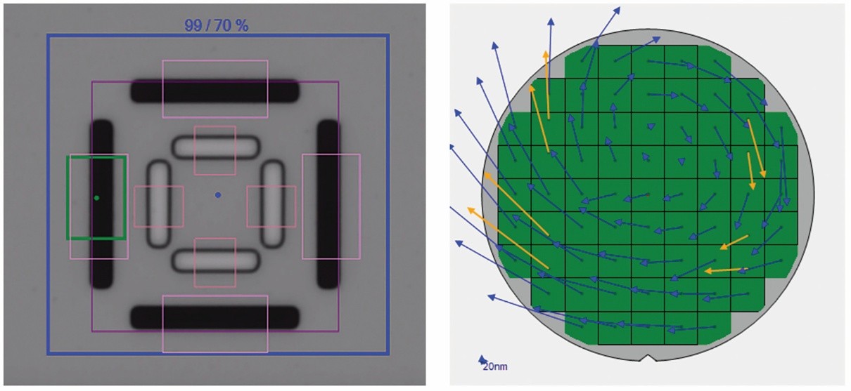
Optically opaque materials present a series of challenges for alignment and overlay in the semi-damascene process flow or after the processing of the magnetic tunnel junction (MTJ) of a Magnetic Random-Access Memory (MRAM). The overlay and alignment of a lithographically defined pattern on top of the pattern and the underlying layer is fundamental to device operation in all multi-layer patterned process flows. There are a wide variety of optical techniques and specially designed targets (Figure 2) that are used to address this problem in conventional flows. Typically, either an ultraviolet, visible, or infrared light is coupled through the top photoresist layer or an etched hard mask to be aligned to the bottom layer [1]. However, in some MRAM flows this coupling may not be possible as there may be an intervening opaque layer (Figure 1). In such cases, conventional methods of alignment using light fail. To overcome this issue, extra patterning operations may be used to open areas around the alignment features, but these operations add significant process cost.
In this paper we evaluate the use of picosecond laser acoustics (PLA) measurement as an alternative method to characterize the overlay and alignment patterns that are embedded under opaque metal films. We selected the MRAM process flow for this study where the different overlay and alignment markers were underneath opaque layers including an MTJ layer. These specific markers are imaged with the help of PLA employing an ultrafast laser in a pump and probe configuration to generate and detect acoustic waves capable of propagating through optically opaque layers. This technique, in sharp contrast with other competing acoustic imaging techniques such as scanning acoustic microscopy (SAM) [5,6], does not require the sample to be submerged in a coupling medium such as water.