
Abstract
The growing demand for heterogeneous integration is driven by the 5G market. This includes smartphones, data centers, servers, high-performance computing (HPC), artificial intelligence (AI) and internet of things (IoT) applications. Next-generation packaging technologies require tighter overlay to accommodate larger package sizes with fine-pitch chip interconnects on large-format flexible panels. Heterogeneous integration enables device performance gains by combining multiple silicon nodes and designs inside one package. The package size is expected to grow significantly, increasing to 75mm x 75mm and 150mm x 150mm, within the next few years. For these requirements, an extremely large exposure field fine-resolution lithography solution was proposed to enable packages well over 250mm x 250mm without the need for image stitching, while exceeding the overlay and critical uniformity requirements for these packages.
One of the challenges of extremely large exposure field fine-resolution lithography is to achieve an aggressive overlay number. Formation changes experienced by the panel as a result of thermo, high-pressure and other fan-out processes shift the design location from nominal coordinates; this causes inaccurate overlay and low-overlay yield in the lithography process. Addressing this critical lithography challenge becomes an important task in heterogeneous integration.
In this paper, a 515mm x 510mm Ajinomoto build-up film (ABF)+copper clad laminate (CCL) substrate is selected as the test vehicle. We will analyze the pattern distortion of an ABF+CCL substrate to understand the distribution of translation, rotation, scale, magnification, trap, orthogonality and other errors in the substrate, and then use extremely large exposure field fine-resolution lithography to address the pattern distortion of the substrate. This demonstration will provide an analysis of panel distortion and detail how the extremely large exposure field fine-resolution lithography solution addresses panel distortion to achieve an aggressive overlay number.
FAN-OUT PANEL LEVEL PACKAGING (FOPLP) has multiple benefits in advanced packaging applications, including enhanced connectivity and reduced costs. FOPLP differs from wafer-level packaging processes in that FOPLP utilizes large, rectangular panels rather than the round silicon wafers typically associated with IC manufacture. FOPLP’s rectangular panels more efficiently fit rectangular die, which can reduce costs since manufacturers can process more packages in each run.
Despite many advantages, FOPLP also faces specific challenges, such as yield loss caused by inaccurate die placement and the resulting overlay errors. In this context, dies with unusually large placement errors, or outliers, can be especially troublesome. These outliers cause losses of both the misplaced die and surrounding dies. However, integrating outlier control with feedforward metrology can greatly improve both yield and throughput.
Fan-out processes cut individual dies from the wafer and reconstitute them on a processing substrate separated by additional space. Subsequent steps fabricate redistribution lines in multiple layers and end with the creation of contacts on the surface of the package. The area available for contacts is increased by the additional space between chips, allowing more contacts per chip.
One critical challenge for FOPLP is die-placement error. This error originates during the robotic pick-and place operation in which chips are positioned on the reconstitution substrate. The problem arises when die positions shift during subsequent processing steps. If uncorrected, these die-placement errors can result in overlay errors and reduced yield. While die-placement errors can be measured and corrected, die-by-die in the lithography tool, this greatly reduces throughput. Feedforward lithography, which measures placement errors and calculates corrections in a separate system and then feeds the corrections forward to the lithography system is much faster. Lithography throughput can be further increased by including more than one die in each exposure site and then applying site-by site corrections to the exposures.
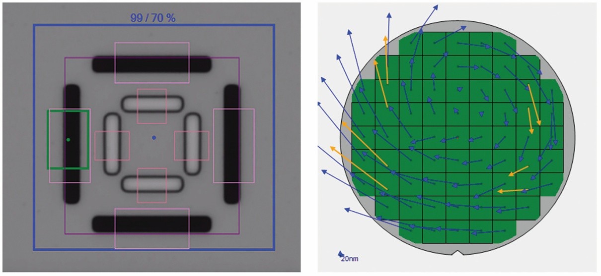
In this scheme, dies with unusually large placement errors can have an outsized impact on yields by skewing the site correction to such a degree that the site correction causes unacceptable overlay errors for all dies in the site. A solution: advanced outlier control technology (Figure 1). This technology detects outliers and excludes them from the correction calculation, thereby sacrificing the outlier to optimize overall yield and throughput.
Rapidly growing demand for new types of functionality across an expanding range of applications, including 5G communication, smartphones, data centers, servers, high- performance computing (HPC), artificial intelligence (AI) and the Internet of Things (IoT), is driving a fundamental shift in the way electronic devices are designed and manufactured. Gone are the days when advances were defined by an increasing number of shrinking transistors with ever-faster switching times and lower power consumption, all fabricated as a single, monolithic integrated circuit (IC). Many of today’s most advanced systems integrate multiple die, each optimized for a specific capability and fabricated with a process designed specifically for that type of circuit. These disparate chips are then connected using advanced packaging (AP) technologies, a process known as heterogeneous integration (HI).
One example of HI uses advanced IC substrates (AICS) in a process known as ultra-high density (UHD) panel fan-out. This fan-out panel level process (FOPLP) is a redistribution lines (RDL)-first approach, where many layers of patterned conductive and insulating material are processed on both sides of a large panel to route electrical signals between the integrated chips, which are added last. Once the RDL layers are complete, solder bumps are added to form connection points that will mate with matching connection pads on the component ICs. Package substrate sizes are expected to reach 150mm x 150mm in the next few years. Panels, which may be 500mm x 500mm or larger, can accommodate many more packages per panel than the substrates used in wafer-level processes, which are restricted to round, wafer-like substrates of 300mm or less in diameter.
The lithography challenge for large heterogeneous integration is the limited size of the exposure field (typically 60mm x 60mm or less) for most currently available lithography systems. Smaller-field systems can be used to pattern large substrates by stitching together multiple exposures, but this affects both productivity and yield because of the need for multiple exposures of multiple reticles and the risk of errors at the stitching boundaries. A large exposure field would eliminate these impediments. However, there are also challenges associated with a large exposure field. These include panel warpage and distortion, which can impact critical dimensions, uniformity and overlay.
We describe here the use of our large-field lithography system (JetStep® X500) to expose 250mm x 250mm substrates in a single shot on 515mm x 510mm panels. Our evaluation included: 1) critical dimension (CD) control for 3m, 5µm and 6µm lines/spaces, and 15μm and 20μm vias; 2) CD uniformity across the exposure field; and 3) overlay accuracy. We used copper clad laminate (CCL) and Anjinomoto build-up film (ABF) panels for resolution, and glass panels with liquid resist for overlay and uniformity. The large field eliminates stitching, allows the exposure of more large package substrates in a single shot and requires fewer shots to complete a panel. We compares the exposure layout for a large field (250mm x 250mm) and a smaller field (59mm x 59mm) on a 510mm x 515mm panel. With the large exposure field, the panel can be completely exposed with just four shots, while the smaller field requires 64 shots.
The growing demand for heterogeneous integration is driven by the 5G market that includes smartphones, data centers, servers, HPC, AI and IoT applications. Next-generation packaging technologies require tighter overlay to accommodate a larger package size with finer pitch chip interconnects on large format flexible panels.
Fan-out panel level packaging (FOPLP) is one of the technologies that is able to achieve market requirements, but also faces several signification processes challenges. One critical challenge for FOPLP is die placement error, which is a result of the reconstitution process. Die placement error can cause high overlay error, which induces low overlay yield. To address this situation, site by site correction exposure with feedforward lithography is proposed. Site by site correction exposure can overcome the die placement error to achieve an acceptable overlay yield, and feedforward lithography is used to improve the throughput when using site by site correction exposure. An issue was observed when using feedforward site by site correction method: when one or more reconstituted dies suffered large displacement error, these large error dies affect the correctable accuracy of the site and induce poor overlay to all the dies in the site. To address this issue, which could induce poor overlay, advanced outlier control technology is proposed. Advanced outlier control technology is used for identifying the large error dies and processing these large error dies to prevent the situation.
In this paper, we demonstrated advanced outlier control technology with feedforward lithography on a selected test vehicle, which is a 510 mm x 515 mm panel. 400 simulation dies were built on this panel and part of the dies were designed with a large displacement error. The panel was processed using advanced outlier control technology with feedforward lithography in the demonstration. This demonstration showed how these two technologies integrated together and how this integration strategy worked for the FOPLP process. We also review and discuss the results for how this integration technology can maintain yield and throughput under such challenging conditions.
The growing demand for heterogeneous integration is driven by the 5G market that includes smartphones, data centers, servers, HPC, AI and IoT applications. Next-generation packaging technologies require tighter overlay to accommodate a larger package size with finer pitch chip interconnects on large format flexible panels.
Heterogeneous integration enables next-generation device performance gains by combining multiple silicon nodes and designs inside one package. The package size is expected to grow significantly, increasing to 75 x 75 mm and 150 x 150 mm, within the next few years. For these requirements, an extremely large exposure field with fine resolution lithography will enable packages well over 250 x 250 mm without the need for image stitching while exceeding aggressive overlay and critical uniformity requirements for these packages.
The lithography challenge to fulfill the need of heterogeneous integration is the limitation of exposure field size of the currently available solutions in the market. Multiple shots with stitching is used and this affects not only productivity performance but potential yield loss at the stitching boundary. Addressing the critical lithography challenges described above becomes an important task in heterogeneous integration, and an extremely large exposure field with fine resolution lithography is one of the best solutions for this task.
In this paper, a 515 mm x 510 mm panel is selected as the test vehicle, and we will demonstrate an extremely large exposure field with fine resolution technology on this panel. This demonstration provides the results and details about how this new technology will address the challenges of large package size processes.
Fan-out wafer level packaging (FOWLP) is a popular new packaging technology that allows the user to increase I/O in a smaller IC size than fan-in wafer level packaging. Market drivers such as 5G, IoT, mobile and AI will all use this technology. According to Yole Développement’s analysis, the fan-out packaging market size will increase to $3 billion in 2022 from $2.44 hundred million in 2014, validating the market requirement for fan out packaging. While FOWLP has been used for many years, there is still a relentless drive to reduce the cost, and fan-out panel level packaging (FOPLP) has been proposed as one possible solution. FOPLP allows users to put more chips on a substrate, meaning more product output and a higher substrate utilization percentage. According to Yole’s analysis, the FOPLP market size will increase to $2.79 hundred million with 79% CAGR, showing that more people are adopting FOPLP.
FOPLP has many advantages and low cost potential, but it faces significant process challenges, such as die placement error and substrate warpage control. One of the key challenges is the trade-off between overlay, yield, and throughput during the lithography processing steps. A user exposes multiple dies per exposure shot to increase throughput, but this can result in lower overlay yield because of “pick and place” die placement error. To overcome the low yield issue, each die needs to be aligned, but this impacts throughput, so a compromise is required. To find the balance point between throughput and overlay is one of the biggest challenges for FOPLP.
In this paper we address the tradeoff between throughputs and overlay yield, we demonstrate an integrated feedforward adaptive shot solution. This feedforward approach uses a third party metrology system to measure reconstituted panel die location data and sends the data to the stepper via a network. With feedforward algorithm technology, the stepper uses smart adaptive shot technology to generate an optimized variable shot size layout. This layout ensures the overlay yield is within specification with the minimum number of exposure steps. With feedforward adaptive shot technology, the user can maximize the throughput of the stepper and ensure the overlay yield at the same time.
Key words: advanced packaging, die placement error, FOWLP, FOPLP, overlay, yield, feedforward.