
Unlocking Scalable SRG Waveguides for Mass‑Market AR/MR Displays
From consumer products to industrial applications, augmented reality (AR)/mixed reality (MR) technology is one of the most innovative interactive technologies on the market today. By overlaying digital information onto the physical world, AR/MR technology improves how people see, understand, and interact with their environment in real time. The industrial applications alone are cause for celebration, whether this technology is being used for training, assembly, or troubleshooting.
Be that as it may, one of the most significant challenges facing AR/MR lies in manufacturing the photonic components that control how light is generated, diffracted, guided, and delivered to the human eye.
An AR display usually consists of a light engine and an optical combiner. The light engine serves as a display image source, while the combiner delivers the displayed images to the viewer’s eye and transmits environment light (Figure 1). Surface relief grating (SRG) waveguides play a role in these optical combiners by coupling display light into, expanding it within, and diffracting it out of a transparent substrate toward the eye of the intended viewer. This component must deliver precise diffraction behavior while remaining transparent, lightweight, and scalable for high-volume manufacturing (HVM).
Balancing optical performance and manufacturability, however, places significant demands on fabrication and process control. Faced with this obstacle, device makers require solutions capable of addressing any negative impacts to launch timelines, unit costs, and OEM qualification.

Figure 1. Diagram of SRG waveguide-based AR display.
In this article we will discuss ways SRG manufacturers can address these challenges with an integrated process control solution tailored for the HVM of SRG. The solution combines optical critical dimension (OCD) metrology for the critical parameters of SRG such as grating depth, slanted angle, and periods; picosecond ultrasonic technology for the metal film thickness measurement; image‑based overlay (IBO) for precise overlay control in HVM specialty devices; and an automated optical inspection for defects integrated throughout the entire manufacturing process.
With these tools combined in a closed‑loop process control strategy, manufacturers have a framework that enables the consistent manufacturing of full‑color SRG waveguides capable of meeting the stringent optical and mechanical requirements of next‑generation AR/MR devices.
Navigating the Ramp to HVM
By coupling light into and out of a transparent substrate through precisely engineered diffraction gratings, SRG waveguides can deliver wide field‑of‑view, high brightness, and compact form factors. Unfortunately, manufacturers of SRG waveguides must face a host of challenges arising from multi‑layer and often double‑sided fabrication, with sub‑100nm alignment tolerances across large‑area substrates, if they hope to transition to HVM. The impact of these challenges, however, only grows as the manufacturing process goes on, increasing yield variability and making it difficult for makers of SRG components to meet the requirements expected by tier-one AR/MR customers.
To begin with, let’s turn to grating geometry. Manufacturers must control for period, depth, and slanted angle to ensure diffraction efficiency and uniformity across the field. Additionally, makers of these components must maintain proper thickness uniformity to avoid phase errors and color shifts; as such, thin‑film processes like mask deposition and etching must maintain exceptional thickness uniformity. Third, manufacturers must also maintain overlay accuracy between lithography steps, and they must do so within a fraction of the design tolerance to preserve red, green, and blue (RGB) multi‑period grating registration and double‑sided alignment. Finally, defect control is essential in the manufacturing process. After all, particles, scratches, and etch anomalies can cause scattering, reduce optical efficiency, and degrade image quality. Not surprisingly, the manufacturing process features a number of consequential steps (Figure 2).
In many cases, the process begins with the deposition of a chromium (Cr) hard mask on a SiO₂ substrate, followed by spin coating a resist layer. For master fabrication, electron beam lithography or deep ultraviolet lithography is used to pattern the grating structure. The resist pattern is then transferred to the Cr layer using a dry etching process, after which the residual resist is removed, leaving the Cr layer to serve as an etching mask for reactive-ion beam etching (RIBE). During RIBE, ionized argon beams are directed toward the substrate at an oblique angle to form the slanted grating profile. Once the target etch depth is achieved, the Cr layer is removed by chemical wet etching.
For HVM, the fabricated master grating is replicated using nanoimprint lithography (NIL) production due to its low cost and high throughput. In this process, the master pattern is first transferred into a polymer film to form a soft working stamp, which is then used to imprint a high refractive index (RI) resist layer. After imprinting, the pattern in the high-RI resist retains the same orientation as the original NIL template.

Figure 2. Basic flow in the manufacturing process of the surface relief grating waveguide.
These manufacturing challenges—spanning nanoscale grating fidelity, thin-film uniformity, overlay accuracy, and defect control—are tightly coupled and cannot be addressed in isolation without compromising yield or optical performance. Achieving stable, HVM requires coordinated visibility into each step of the SRG process. As it stands, makers of waveguide components rely on isolated measurements that diagnose symptoms without revealing root causes. In contrast, an integrated, closed-loop approach connects thickness, CD, overlay, and defect data, allowing engineers to correct process drift before it impacts customer-visible performance. By applying integrated metal film metrology, OCD measurement, image-based overlay control, and advanced defect inspection to the process flow, manufacturers are able to establish control and consistent SRG waveguide manufacturing, improving yield during ramp and reducing qualification cycle times, an important win for manufacturers ramping up HVM.
Tackling Thickness Non-Uniformity
As part of this integrated process control framework, thickness uniformity is a critical variable to address. In SRG manufacturing, thickness and uniformity must be precisely measured and controlled as it directly impacts downstream etch behavior, grating geometry, and ultimately optical performance. Uncontrolled metal film thickness is a frequent root cause of profile distortion and yield loss in SRG waveguides. When combined with CD, overlay, and defect control, the ability to measure metal thickness enables full process visibility across SRG manufacturing.
After deposition, the hard mask must be thick enough to remain intact throughout the entire etching process without being prematurely etched through. However, excessive thickness can distort the etched sidewall profile. Moreover, non-uniform thickness across the wafer can lead to variations in etch depth and grating tilt angle. This degrades diffraction efficiency and wavefront quality.

Figure 3. Cr and Al spectra and measurement result mapping.
To measure thickness, makers of SRG components can use an inline metal film metrology tool with picosecond ultrasonic technology. This tool offers rapid and precise determination of Al/Cr thickness across different substrates, delivering within wafer uniformity characterization that facilitates the early identification of process deviations.
In our demonstrations, we used an inline metal film metrology tool to gather data. The metrology system can measure metal film thickness across the wafer and with repeatable, stable precision over time, making it suitable for tight process control in high-volume SRG waveguide manufacturing. In production demonstrations, the results showed high-precision metal film thickness measurements with strong wafer-level uniformity and repeatability across representative substrates and multilayer film stacks (Figure 3). In addition, the metal film metrology tool achieved outstanding dynamic and static stability, thereby ensuring compliance with the rigorous demands of advanced process control as shown in Table 1. This level of control offered by the inline metal film metrology tool directly reduces grating profile drift between lots, lowering rework rates and preventing late-stage optical fallout during customer acceptance testing.
| Film information | Wafer Uniformity | Repeatability(1σ) | |||
| Average | Stdev | 1 σ | Static | Dynamic | |
| Si/Al3000Å | 2676.7 | 53.4 | 2.00% | 0.03% | 0.01% |
| Glass/Resin5000Å/Al3000Å | 2706.8 | 52.2 | 1.93% | 0.10% | 0.04% |
| Si/Cr220Å | 215.1 | 3.6 | 1.66% | 0.04% | 0.00% |
| Glass/TiO2600Å/Cr220Å | 223.2 | 4.5 | 1.99% | 0.15% | 0.10% |
Table 1. Cr and Al wafer uniformity and repeatability.
Meeting Tight Design Tolerances with OCD Metrology
In the fabrication of SRG waveguides, optical performance is highly sensitive to nanometer scale variations in grating period, depth, sidewall angle, and fill factor. Manufacturers of these components must adhere to the extremely tight design tolerances required for target coupling efficiency, polarization control, and chromatic uniformity throughout the manufacturing process.
To accomplish this, manufacturers can deploy OCD metrology based on rigorous coupled wave analysis (RCWA) to continuously monitor grating depth, CD, and sidewall angle before optical deviations propagate downstream. In demonstrations, we used an OCD metrology system based on RCWA to decode light scattering signals and simultaneously extract grating parameters across the entire wafer. Two types of SRGs were targeted: blazed SRGs and binary SRGs. Binary SRGs use a two-level stepped profile for phase or polarization control, and blazed SRGs use a slanted or ramped profile to efficiently direct light into a preferred direction.
Using OCD metrology, measurements of key parameters showed excellent agreement with reference metrology in representative SRG structures, confirming the suitability of OCD metrology for process control in SRG manufacturing. This stability enables tighter process windows and allows manufacturers to run closer to design limits without sacrificing yield, a critical need in situations where OEM specifications leave little margin.


Figure 4 .(a) OCD mode of blazed SRGs, matching with reference and dynamic performance. (b) OCD mode of binary SRGs, matching with reference and dynamic performance.
Preserving Full-Color Performance Through Precise Overlay
For manufacturers, maintaining overlay accuracy between successive patterning steps is a critical determinant of optical performance. Even small misalignments can cause coupling efficiency loss, field-of-view distortion, polarization imbalance, and chromatic aberrations.
Although a single SRG is typically formed in one patterning step, waveguide processes often require multiple patterning steps or the integration of several functional gratings on the same substrate. Representative cases include separate in-coupling and out-coupling gratings, multiwavelength gratings for full color operation, where red, green, and blue gratings of different periods are overlaid in the same location via multiple lithography or multiple nanoimprint patterning steps performed on both sides of the substrate, and precise registration with other micro-optical structures. These scenarios have stringent requirements. As such, overlay control at the submicron level is needed to preserve designed optical characteristics. Meeting these stringent alignment requirements in SRG waveguide architectures necessitates precise, wafer-scale overlay metrology. IBO techniques provide component makers with the capability to directly measure and control cross-layer and double-sided alignment in transparent substrates.

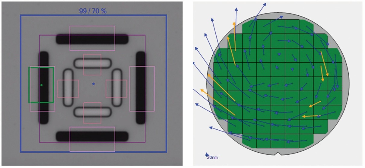
Figure 5. Bar-in-bar (BIB) and overlay fingerprint.
For our demonstration we used IBO technology enabling cross-layer and double-sided alignment in transparent waveguide substrates by matching grating pattern features. Using a bar-in-bar (BIB) mark for full map overlay measurement, demonstration measurements showed that the system achieved a precision of 0.26nm (X) and 0.18nm (Y) at 3σ (Figure 5). The measured tool-induced shift (TIS) was -2.63nm (X) and -0.71nm (Y), with corresponding 3σ TIS values of 0.62nm and 0.81nm, respectively (Table 2). Based on the industry standard 3σ definition, the resulting total measurement uncertainty (TMU) was 0.83nm in the X direction and 0.92nm in the Y direction. These results demonstrate that the overlay platform delivers sub-nanometer overlay capability and provides sufficient margin for the alignment requirements of high precision, full-color SRG waveguide manufacturing. In addition, the system provides correction parameters that can be directly applied to the lithography tool to compensate for systematic overlay errors.
| RG X Avg (nm) | RG Y Avg (nm) | RG X 3S (nm) | RG Y 3S (nm) | TIS X Avg (nm) | TIS Y AVG (nm) | TIS 3σ X (nm) | TIS 3σ Y (nm) |
| -71.8 | 36.0 | 0.3 | 0.2 | -2.6 | -0.7 | 0.6 | 0.8 |
Table 2. Overlay measurement statistics.
Detecting Submicron Defects
Defect inspection is critical to the manufacturing of SRG waveguides. Due to the unique nanoscale periodic structures and the optical sensitivity of SRG waveguides, even minor defects can lead to reduced diffraction efficiency, increased stray light, image non-uniformity, and other issues. As a result, defect inspection should be integrated throughout the entire SRG manufacturing process. In the mass production of SRG waveguides using NIL, manufacturers are enabled to detect organic defects from the photo resist, cleaning chemical residues, and high index resin which would normally escape detection under conventional brightfield or darkfield illumination schemes. In HVM undetected submicron organic defects can propagate across replicated stamps, turning a localized issue into a systemic yield problem.
The automated defect inspection system we employed provides fast and reliable inspection for submicron defects and the option to accurately measure 2D and 3D metrology features. Equipped with multiple illumination technologies, the inspection system is capable of capturing organic defects at or below 1µm. Standard optical inspection struggles with features at this size, opening the door to defect contamination that would otherwise be invisible but detrimental.
The Continued Evolution of AR/MR Technology
With the advent of mass production and declining costs of SRG waveguides, the coming years are poised to mark a transformative phase for AR/MR technology. This article presents an approach for full process control for the HVM of SRG waveguides, encompassing metal film metrology, OCD measurements of grating parameters, overlay alignment verification, and defect inspection—spanning from incoming substrate qualification to the validation of the final product.
The process‑control challenges discussed in this article extend across a broad class of AR/MR optical architectures, diffractive and meta-optical devices, and other nano-patterned optics manufactured at scale. Beyond SRG waveguides, the same process-control capabilities extend across a wide range of optical and photonic manufacturing applications, including other AR/MR waveguide architectures such as volume holographic and multi-level diffractive waveguides, as well as diffractive optical elements and meta-optics that rely on sub-wavelength pattern fidelity and precise depth control. These applications overlap strongly with optical thin-film stacks and functional coatings, micro-display manufacturing, and advanced optical and silicon-photonics packaging, all of which demand tight control of CD, overlay, film uniformity, and defectivity to reach HVM.
For manufacturers evaluating their next waveguide ramp, the key question is no longer whether SRG waveguides can meet optical targets, but whether their process control strategy can meet OEM schedules, cost models, and yield expectations at the same time. With the right integration of tools on hand, they can.
Biography
Alex Hong is a Senior Field Application Engineer at Onto Innovation, specializing in metal film metrology for semiconductor manufacturing, with additional expertise in optical critical dimension (OCD) applications.
The author would like to thank the rest of the team who worked on this article, including Onto Innovation’s Huayuan Li, Charles Zhang, Yuhang Lin, and Johnny Mu, along with Xiongwei Wang and Chenglong Jia of Sunny Optical Oulai Micro-Nano Optics (Shanghai) Co., Ltd.

You Have a Challenge? Let’s talk.
We’d love to connect with you.
Looking to learn more about our innovative solutions and capabilities? Our team of experts is ready to assist you. Reach out today and let’s starts a conversation about how we can help you achieve your goals.
Let’s Talk
"*" indicates required fields